| Basic theory behind transmission line
design The transmission line system is
a waveguide system in which the guide
reverses the phase of the driver's rear
output, thereby reinforcing the
frequencies near the driver's Fs. Unlike
sealed, ported and bandpass systems,
transmission line systems are
theoretically non-resonant, and therefore
are capable of producing very clean and
uncolored bass - if done properly! The
transmission line system affords
uncolored sound due to the lack of system
and cabinet resonances, provides extended
bass support, and all at moderate
efficiency.
Transmission lines tend to be larger
than the other systems, due to the size
and length of the line required by the
design. Theoretically, the length of line
should be 1/4, 1/2 or 3/4 of the
wavelength of Fs, however shorter lengths
will work if stuffing is used within the
line to increase its effective length
(sound travels more slowly through the
stuffing). Designs that use the shorter
(1/4 wavelength) lines generally require
more care and attention in getting the
stuffing right - but you end up with a
smaller box - and greater SAF!
Usually, only drivers which have low
Qts (0.25 - 0.4) , Qes (0.3 - 0.4) and Fs
values are suitable for transmission line
systems.
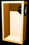
Think of a TL as a pipe containing a
driver in one end and with the other end
open. A TL has no tuning frequency (Fb)
like a sealed or ported box.
"Tuning" a TL is a simple
matter of making the line length 1/4
wavelength of where the driver begins to
roll off, so that the rear wave can
reinforce the front wave. The line may be
tuned to either the driver's F3 (-3 dB)
or F10 (-10 dB), depending on whose
design methodology you use. Similarly,
unlike a port, which acts as a Helmholtz
resonator, the parameters of a TL are
independent, the cross-sectional area
being determined by the driver's Sd, and
the length being determined by the
driver's F3 or F10, as previously noted.
Some TL's (notably the Focal Daline
series) are a hybrid, utilizing a small
enclosure which vents to the outside via
a more conventional TL. Even in a Daline,
though, the cross sectional area of the
TL where it joins the box is much larger
than a typical port, usually 1-1.5 times
the SD of the driver. TL's are usually
stuffed, often with stuffing materials of
varying density. Unlike sealed
enclosures, the stuffing in a TL is used
to reduce the speed of sound through the
line. There is no significant increase in
efficiency over a sealed box. Response
rolls off at a 12 dB/octave slope, just
as in open-air mounting or a sealed box.
To contruct a transmission line
system, you first need to start with a
suitable driver. Suitable drivers have a
fairly high Qms (3 to 6), a fairly low
Qes (0.30 to 0.40) and a correspondingly
low Qts (0.30 - 0.40). Experienced
transmission line builders normally stick
to a few brands and models of drivers
that are known to work well in this type
of application.
Choosing the length of the line:
Secondly, you'll need to choose what
length transmission line you're aiming
for. The theoretical line length will
have to be 1/4, 1/2, or 3/4 the
wavelength at the driver's Fs. A short
list of sample lengths is given below.
The lengths are based on a figure of
341m/s for the speed of sound:
These lengths are in most
circumstances much too long to use in any
practical speaker design. However, if the
line is stuffed with wool or other
damping material, shorter lengths can be
used. For example, for a 100% stuffed
line (wool), the corresponding lengths
would be:
The 100% wool damping has the added
effect of damping any resonances that may
develop within the line itself.
Based on the above figures, it makes
sense to choose a line length that is a
bit longer than those given by the second
set of figures, then tune it to the
correct frequency by adding wool or
another similar damping material. until
the line is tuned to the correct
frequency.
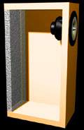
Stuffing the Line:
Fill the 1st 1/6 of the line with
long hair wool .5 lb per Ft^3, the next
1/3 with a mixture of 50% wool 50%
Acousta-Stuf at the same density, the
next 1/3 Acousta-Stuf at the same
density, then leave the last 1/6 empty.
Measure the output of the driver using
a mike less than 3 inches from the cone,
then measure the frequency respons of the
port with the mike in the port. The port
will usually have significant out put for
several octaves. The trick is to damp
(stuff) the system until the port output
compliments the driver output. As you add
stuffing you are attenuating the higher
frequencies and lowering the lower
frequencies. Wool absorbs higher
frequencies, Acousta-Stuf is better at
bass frequncies. An example of the
measured port and driver outputs is shown
below:
And below is the actual measured output
of one transmission line system (click on
image to see the full size version of the
graph):
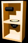
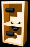
Tapering the Line:
For the best results, the line's
cross-section should taper down from its
start point at the driver to its finish
at the port. A good method to do this is
to start with a cross-section that's
twice the driver's radiating area, then
tape this down to a port that's 70% of
the driver's radiating area. The line can
be folded a few times to fit it in a
decently-sized box - this will also tend
to reduce the line's tendency to resonate
at other frequencies and color the output
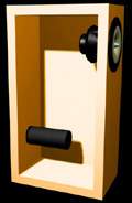
at the port. A sample transmission line
showing one method of incorporating the
line in the design is shown below:
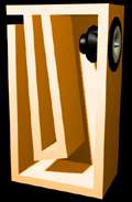
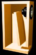
Bends and end effects:
For a 90 degree bend in the line, the
line length is effectively reduced by
0.4*r, where r is the radius of the bend.
For a 180 degree bend, the effective
length is reduced by 1.0*r. If the end of
the line is free, the effective length is
increased by 0.58*r, where r is the
radius of the opening. For a flanged end
(the normal case), the effective length
is increased by 0.82*r. If the opening is
placed close to a surface (like the
example above), the effective length is
increased by 1*r.
Classic Transmission LineRules of
Thumb
--------------------------------------------------------------------------------
make the line length ~ 1/4 the wavelength
of Fs (1/4 wavelength will be the F3
point)
taper the line from 1.25 - 2 Sd down to
Sd at the port
after building it, stuff the line --
increasing or decreasing the stuffing
till it sounds right. Add if the line is
too "boomy", reduce if its too
lean. The stuffing increases the length
of the line (by slowing the speed of
sound down to .7-.9) and (hopefully)
damps out higher frequencies.
These rules seemed to work fairly well
and were based on the available lit plus
the dissasembly of a number of Fried,
Rogers & IMF tlines.
|