 |
|
driver's motor |
|||||||||||||||||||||||||
| general structure |
|
||||||||||||||||||||||||
| Speaker's drive engine is all to often seen as
passive element, which only converts electrical energy to
mechanical. Although voice coil is always immersed in a
fixed magnetic field, it acts as a part time motor, part
time generator. When loudspeaker is driven with a signal
from the amp, this signal causes the voice coil to move
in the magnet field and then impart its movement on the
cone to produce the acoustic signal. But, as soon as the
signal from the amp goes away, the cone and voice coil
start to fall back to the zero position, or no-signal
position. As the voice coil is moving back 'home', the
windings of the coil cut across magnetic lines of force
in that fixed magnetic field and the result is that a
voltage is developed in the voice coil. It has now
changed operation from a motor to a generator. The
generated voltage is called back EMF, or flyback, and is
fed back up the line into the amp and appears in the
output circuit. This voltage would continue to be
generated until the cone stopped vibrating and finally
came to a rest at its home position. One way to stop the
oscillations is to make it difficult for them to occur.
The easiest way is to put a big load on the voice coil
when it is in its generating mode of operation. Ever
notice when you turn on the rear defogger in your car,
the engine idle RPM goes down slightly? That's because
the defogger requires quite a bit of current to operate
so the load it puts on the alternator makes it more
difficult for the engine to turn the alternator. You can
take any simple permanent magnet motor, such as that used
on a slot car or other toy car, and after temporarily
shorting the terminals together, you'll notice it is more
difficult to spin than with the terminals open circuit.
This is electrical damping. The ratio of this internal source impedance to the suggested speaker load impedance is called the damping factor, and is usually at least 5 or higher. The higher the number, the better, generally, and is a measure of how well the output circuit will quench or stall the oscillations in the speaker by providing a big electrical load to them during the time the voice coil is acting like a generator. Of course, the resulting electrical power doesn't just disappear, it ends up in the output circuit of the amp where it is dissipated as heat. It's odd to think of the output tubes acting as a dummy load for this flyback power, but that's how it works. Output tube bias, transformer turns ratio, and wire sizes all affect the damping to some degree. Sometimes those flyback voltages from the voice coil we spoke of earlier can get quite large. If you ever see a schematic of a guitar amp and notice the designer has installed solid state diodes between the plates of the output tubes and ground, it is to help quench those flyback voltage spikes. Eddy Currents: When inductance is applied to an iron core, voltage is induced in the core. The eddy current flows in opposite direction to the coil flux, which results in power loss and increased distortion. Eddy currents are negligible in a air cores because voltage isn't induced in a non-magnetic core. Saturation: Induction decreases when more power is applied. The reason for this inverse relation is when all the magnetic lines of induction become full, or saturated, only a small additional amount of induction can be produced which leads to distortion. Iron cores often become saturated 2 or 3 times faster than air core inductors. Hystereses Losses: Magnetism is induced in an iron core when voltage is applied to it, magnetizing the core in one direction. Additional power is needed to reverse the magnetic field, and the reversal may not be instantaneous resulting in unwanted distortion. Therefore, air cores have substantially reduced hystereses distortion due to the fact that they have no magnetic core. It should be noted that Hystereses becomes greater at higher frequencies since the frequency changes much more rapidly , in excess of 20,000 times per second (20KHz). |
|||||||||||||||||||||||||
| There are different ways to make voice coils,
egewound, non-egewound, and multi-layer. Egewound coils
can fit more turns of wire on a voice coil since the wire
is flattened and wound on its edge. Standard coils are
just circular wire with no special properties.
Multi-layer are generally used in subwoofers where two
channels are to come out of one speaker. The disadvantage
of this and the resulting unsuitablility for small
speakers is the increased inductance which reduces higher
frequency output. Loudspeaker voice coils when driven at high power levels experience considerable heating which results in elevated voice coil resistance and subsequent damping loss. This is often called power compression. Most voice coils use copper wire, however, aluminum wire was used in some ribbon or edgewound coils to save even more weight. Many of the original edgewound coils were short coils, usually just the length of the width of the front plate. These are called the ends of the coil are even with the edge of the front 'even hung' voice coils since platesensitivity, they run out of coil in the gap during . Although even hung coils exhibit more big excursions of the cone the mechanical signal (force) to the . The result is square-waving of conelightweight and has high top note . In other words, it just stops moving. If the cone is very efficiency cone and it can sound , this square-waving can cause ringing and ghost notes in the very harsh manner. The wire. Plain Aluminum will not do, it's resitance
drifts far too much with temperature. I'd have to talk to
a few people to find out what they used back then, all I
know it was some alloy. ''''''''''''''''''''''' Again, in order to get the full range, we have to make all of the components in the speaker system very lightweight. Notice the wasted spaces between the windingsFigure 2 shows how we can , due to the curvature of the round copper wire. eliminate most of the wasted space by using square wirestep further and . If we take it one flatten the wire into a ribbon shapecurrent , we reduce the wasted space and also add more (and power) capability, as shown in Figures 3 and 5. |
|||||||||||||||||||||||||
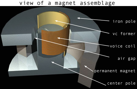
| The voice coil is wrapped around a voice coil former.
The former acts as a support for the voice coil wires, as
well as aiding in the thermal transfer from the coil to
the pole piece. despite the fact that using a paper former is a great marketing tool for vintage style speakers, the fact is it has no effect on the sound itself. It, like Kapton, is a diamagnetic material, and it's effect on the magnetic field and the effect of the magnet field on the former itself is negligible. The big difference is in the mass, or weight of the formers. In the early 70's when the race was on to have the highest powered solid state amp, speaker manufactures had to keep up by making their speakers take alot of power. Therefore, Kapton was put into use. Because the Kapton is thicker, heavier, etc. (a typical one looks like an orange plastic pill bottle), it takes alot of power to get it moving. So, the movement was to heavier Kapton voice coils, heavy, damped cones, and damped surrounds for a high powered, relatively low sensitivity speaker. Now we're going the other way. Low powered amps, light weight speaker components, and high sensitivity to make the lower powered amps sound huge. The one possible exception to the coil former having an effect is the use of an aluminum former. Some believe that since it is a closed loop of metal, there are 'eddy' currents circulating in the former. These eddy currents could affect the sound by causing a braking action to voice coil movement, thereby increasing the damping of the speaker. |
|||||||||||||||||||||||||
| The energy in the gap is called flux. The word flux comes from a Greek word which means 'to flow', allthough flux doesn't flow like current, but is static. It's convenient to think of it as a current, though and the mathematics used in magnetic circuits is very similar to volts/amps/resistance we use in electrical circuits. The concentration of magnet flux in the radial gap around the voice coil is what the voice coil works against to make it move in and out and impart its movement on the cone. The more flux, the better, generally. We usually think of so many lines of flux per square centimeter in the gap. The gap energy of modern speakers is in the range of 10Kgauss to 18Kgauss. That means it has 10,000 to 18,000 lines of flux per square centimeter. The amount of gap energy and the size of the voice coil determine the amount of torque or pulling power one has available to move the cone in response to an input signal. Ideally, the cone, spider, and surround would be very stiff so as to exhibit excellent damping, while the coil and gap energy (called the motor circuit) would be designed to be very powerful. Getting alot of flux (gap energy) in the gap is limited by the size of the magnet, the gap spacing (gap length), and the type of steel used for the magnet circuit steel parts. There's an interesting relationship between the size of the magnet and the gap energy. For instance, if a particular magnetic circuit had an 8oz magnet and had 8,000 gauss of flux in the gap, it would take over 60oz of magnet to double the amount of flux in the gap. It's almost proportional to the square. That's why you see some speakers with huge magnets. In order to get high sensitvity in the speaker using wide gaps, they have to employ a very large magnet. Modern high production volume speaker manufacturers tend to use big gaps so they have less chance of voice coil rubs, and use steel parts with higher carbon content because it is cheaper. The higher carbon content limits the amount of flux the steel can conduct because the carbon acts as a resistance to the conduction of the flux. They compensate by using larger magnets to achieve the flux density they desire. | |||||||||||||||||||||||||
| We feel it is inevitable for a full range moving coil
driver to exhibit this behavior. There may be other ways
to name it and descibe it but to have the excursion and
cone area to effectively create the low frequencies and
having the velocity capabilities for the high frequencies
gives you a unique set of problems. Let me think about
what might be out there as references. We have not
published anything because this was all proprietary until
recently. One of the dictionary definitions of the word
damp is to deaden a shock. In other words, a device or
method is used to stop vibrations or oscillations caused
by mechanical shock. In the case of your automobile, the
shock absorbers deaden the oscillations of the suspension
system in order to make the ride more comfortable and
improve handling. Damping is also very important in
loudspeakers. Quite simply, if the speaker system
consisting of the voice coil, the cone, and the spider
was allowed to vibrate freely without any kind of
damping, it would be very difficult to achieve any kind
of recognizable or useable acoustic signal from it. We
want to be able to blast the speaker with a big signal,
have it respond, then stop vibrating almost instantly
when we remove our signal. |
|||||||||||||||||||||||||
Ceramic Ferrite (Strontium Ferrite) Powdered ferrite magnets were developed using the ceramic process and subsequently became the standard magnet for loudspeakers. They are the cheapest, and most widely used, magnets available on the market today. Alnico AlNiCo is a type of alloy magnet which was used extensively in loudspeakers between 1930 and 1960. As its name suggests this family of alloy magnets employ Aluminum, Nickel, and Cobalt. The most common ones are with marks 2, 5, and 8. Each has its own unique characteristics which generally has to do with how strong they are when magnetized, and how easily the magnet can be demagnetized. For speaker applications, AlNiCo 5 is the best choice in the AlNiCo family of alloy magnets. Its peak energy product is just right for loudspeakers where we need to concentrate high densities of magnetic flux in the gap around the voice coil. AlNiCo 5 is an alloy made up of 8% Aluminum, 14% Nickel, 24% Cobalt, and 3% Copper. AlNiCo 5 is almost universally chosen for loudspeaker use because it has a high flux, and under normal circumstances of use, the speaker wasn't intended to be driven hard enough to affect the magnetism of the magnet by the voice coil magnetism. The price of cobalt began to skyrocket, so the industry was forced to develop other types of magnets. It currently sells for about US $64 a kilo. Most of the worlds supply comes from Zaire. Besides that country controlling the market, cobalt is also a strategic metal used in missles and other weapons systems and cobalt magnets are still the most widely used magnets in the world, being employed in everything from weapons systems to analog meter movements, to debris separator grates in manufacturing processes. Many people, who don't take AlNiCo cult for granted, ask themself why it should be better than ferrite with the same magnetic strenght. The answer lays in Alnico's smooth compression at high average levels. This effects sound simmilar to tube's soft clipping at high outpout powers. Alnico is an alloy magnet and all alloy magnets are easier to demagnetize than comparable ceramic (Strontium Ferrite) magnets. As the voice coil starts moving in response to the input signal, it generates a magnetic field of its own that tries to demagnetize the magnet. As its effect lowers the available magnetic field of the alnico magnet, the speaker becomes less efficient, the voice coil moves less, etc. The physics of it is that the magnet domains near the surface of the magnet poles begin to change state, or flip directions. The result is smooth compression, the same kind of operating curve compression that occurs in a tube amplifier. The ceramic magnet, on the other hand, doesn't compress or demagnetize as easily, so the voice coil moves to its mechanical limit and won't go any farther. This is why many say ceramic magnets sound a little edgey at high average levels as opposed to alnico. If we continue with tube/solid state comparison, then alnico behaves tube-amp like and louder average volumes can be achieved but with smooth compression. The compressing or demagnetization that occurs with the AlNiCo is not permanent. It's domains spring back to their initial state. c Neodimium Neodymium iron boron, a high reminence, high coercivity permanent magnet material, has been in use in the audio industry for several years in the form of small (approximately 1-cm-diam) disks in high-performance microphones. Dropping prices and continuing enhancements in material properties, reducing thermal demagnetization and increasing residual magnetic flux density, have made neodymium more attractive for use in professional audio loudspeakers, where magnent size can reach 4 in. in diameter and almost in. thick. While still considerably more expensive than the more commonly used ferrite ceramic magnets, neodymium magnet structures can be smaller and have a higher flux density than can be practically attined with ceramics. A specific example of loudspeaker motor structure design using neodymium---the Architectural Acoustics Neo Series Acoustical Components from Peavey Electronics---will be presented. Acoustical implications of high-force loudspeakers on enclosure design will also be discussed. [Work supported by Peavey Electronics Corporation.]
CobaltSamarium
|
|||||||||||||||||||||||||
 |
  |